Different clamping components can be attached to the spindle to hold work.
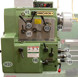
- It can adjust the spindle speed
- Adjustment for feed screw for thread cutting
- Feed adjustment for automatic feed
- Emergency stop button
- Cutting fluid pump switch

| Headstock |
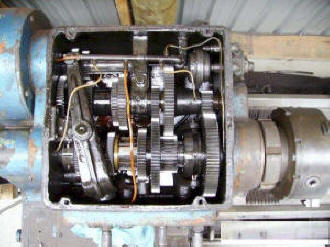
| Head Stock The main function of
headstock is to transmit power to the different parts of a lathe. It
comprises of the headstock casting to accommodate all the parts within
it including gear train arrangement. The main spindle is adjusted in it,
which possesses live centre to which the work can be attached. Different clamping components can be attached to the spindle to hold work.
|
|
| The function of the centre lathe with respect to energy flow. Video |
| The lathe spindle is the main component
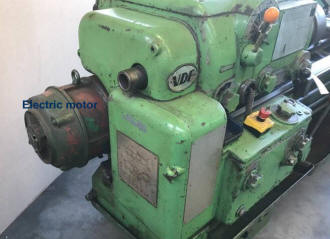
on the lathe. Power transmission begins at the motor shaft. The
shaft is either keyed to a pulley for belt driven lathes or to a gear
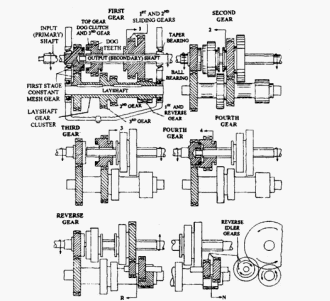
which is engaged with a system of gears (like in a car gear box). Belt driven lathes will have to be stopped to move belt position when changing speeds. Reversing spindle rotation requires the use of an idler. So, using the reverse lever in a lathe engages the idler which reverses the spindle rotation. Gear driven lathes use dog gears to engage different sets of gears for varying speeds. Power transmission is a bit more complex in these lathes and special care has to be taken to ensure metal chips and debris do not enter the gear box. Maintenance on these machines is also a bit more expensive but the power transmission is smooth, compact and easy. The feed shaft and lead shaft is also driven from the gearbox. Feed can be adjusted from the gearbox as well pitch for cutting screw thread with the lead shaft. It must be noted that spindle speeds cant be changed before the motor have not come to a complete stand still. Care must also be taken not to change spindle direction before the motor have come to a complete stand still as failure to do this can lead to severe damage to the gearbox. Chuck can be rocked forward and backwards by hand to facilitate easy gear engagement. Never force gears into position. |
 |
 |
 |
| Spindle speed selection Video | ||
| The lathes are designed to
operate at various spindle speeds for machining of different materials.
There speeds are measured in RPM (revolutions per minute) and are
changed by the cone pulleys or gear levels. One a belt-driven lathe,
various speeds are obtained by changing the flat belt and the back gear
drive. Steps to be followed setting spindle speed:
|