| Type of Gears -
Intersecting Shaft Gears - Straight Bevel Gear |
|
Video |
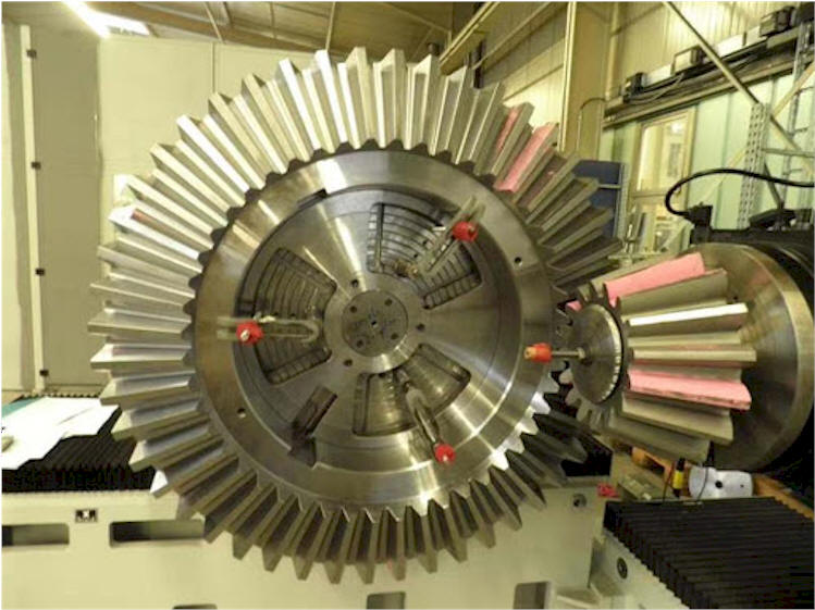
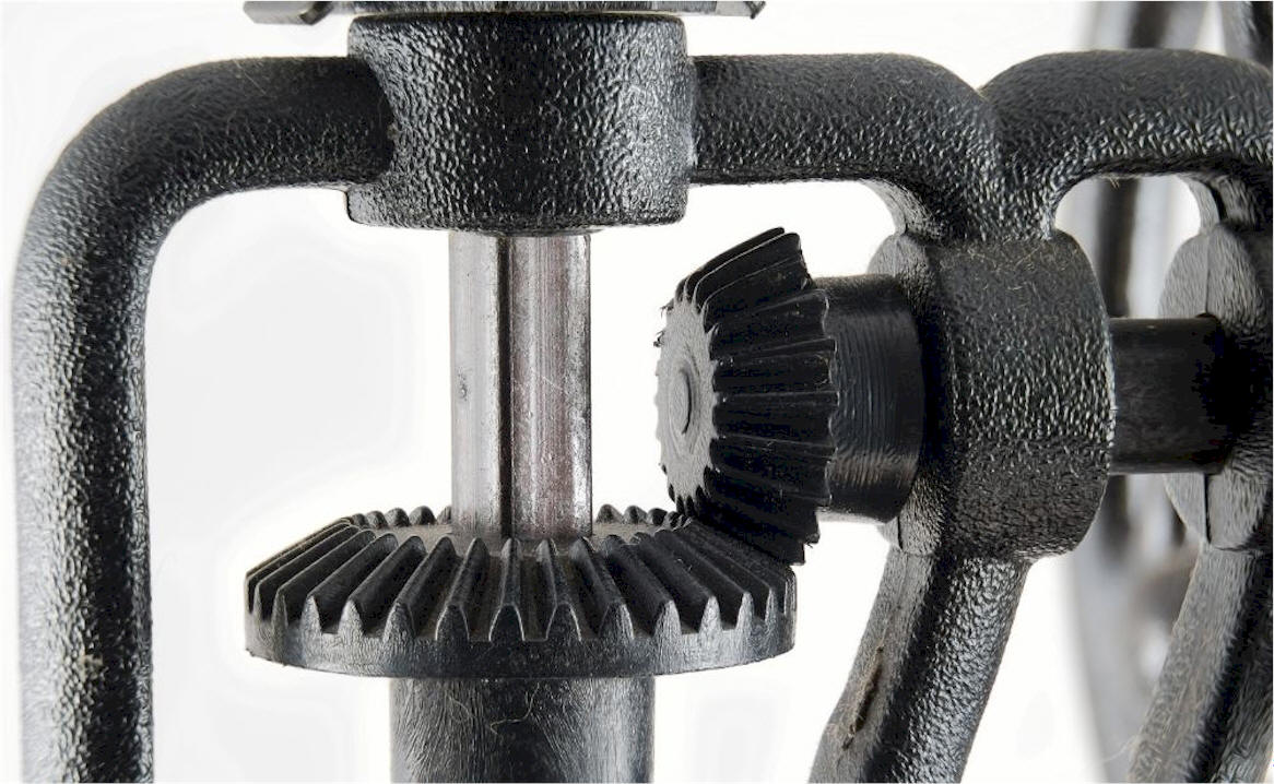
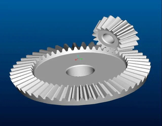
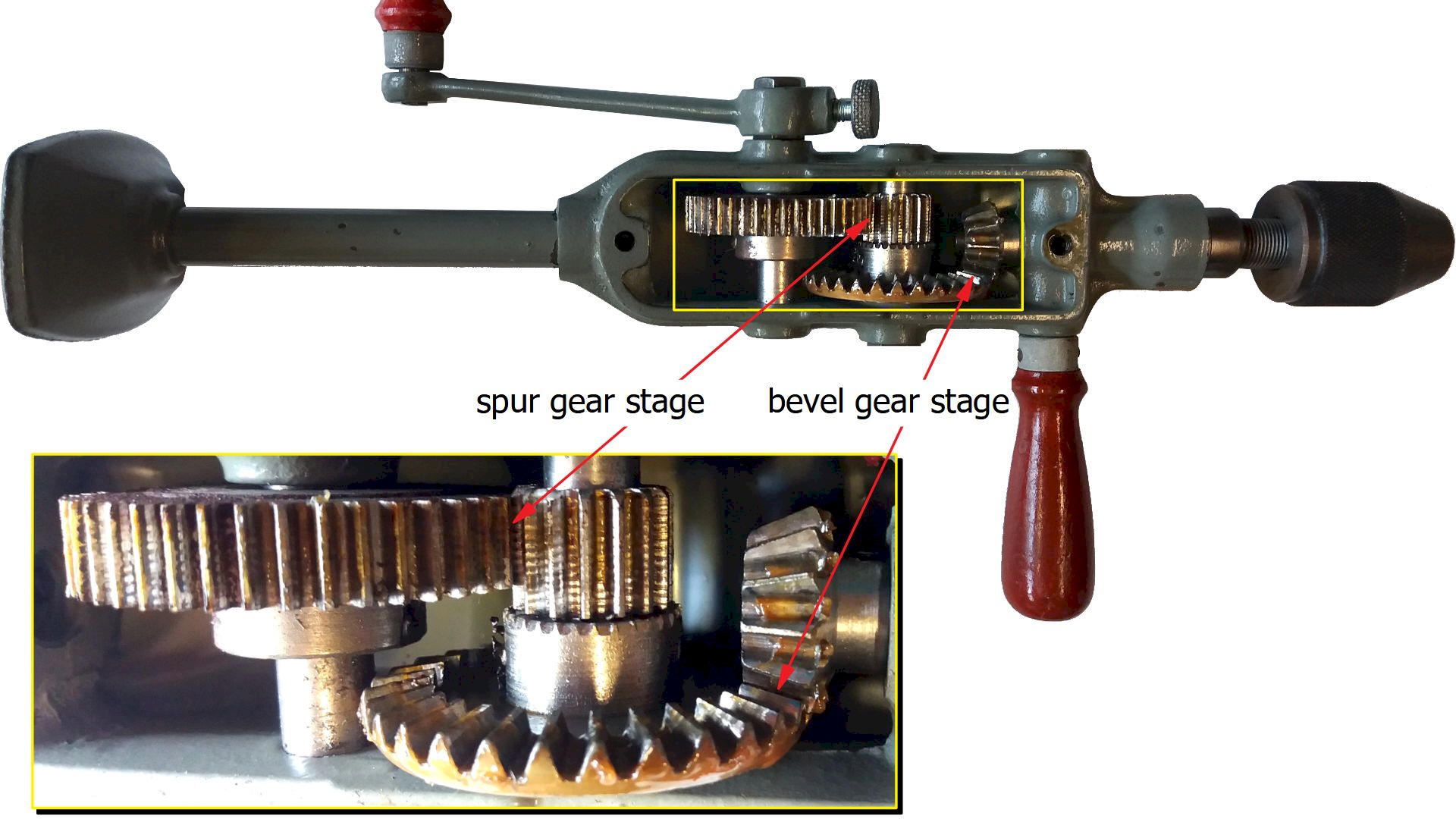
| A straight bevel gear is
the simplest type of bevel gear, used to transmit power between
intersecting shafts, most commonly at a 90 degree angle. Its teeth are
straight and taper toward a single point called the apex, similar to a
spur gear but conical in shape. Straight bevel gears are best for
low-speed applications, as they produce more noise and vibration due to
line contact between the teeth, and are more cost-effective for such
uses. |
| |
| Key features and
advantages: |
-
Cost-effectiveness: Their straightforward design and
manufacturing processes make them a cheaper option compared to more
complex gear types like spiral bevel gears.
Simplicity: The simple and uncomplicated design makes them easier to
manufacture and assemble.
- Ease of
manufacturing: The simpler tooth structure is easier and faster
to produce, making them ideal for mass production.
Lower thrust force: They exert less axial thrust on the bearings
that support the shafts, which simplifies bearing selection and
housing requirements.
- High mounting
tolerance: The simpler design provides greater tolerance for
assembly and mounting.
|
| Disadvantages: |
- Noise and
Vibration: Due to the straight-cut teeth, engagement between
mating gears is sudden and instantaneous (full line contact at
once), which creates impact loading, resulting in significant noise
and vibration, especially at higher speeds.
- Limited Speed:
The noise and vibration issues mean they are not suitable for
high-speed applications and are generally limited to low or moderate
operating speeds.
- Lower Load
Capacity: The impact loading from the abrupt tooth engagement
means that the force is not distributed as evenly across the teeth
as in helical or spiral bevel gears. This limits their ability to
carry heavy loads.
- Shorter Lifespan:
The impact and shock loading on the teeth can lead to higher wear
rates and a shorter overall service life compared to gears with
smoother engagement.
- Sensitivity to
Misalignment: They require precise alignment during installation
to ensure proper tooth contact and prevent premature wear and
failure.
- Less Smooth
Operation: The operation is less smooth than that of spiral
bevel gears, which can be a drawback for applications requiring high
precision and smooth motion.
|
| How they work |
- Shaft
Orientation: The gears are mounted on shafts whose axes
intersect at a single point, known as the apex of the pitch cones.
The most common angle of intersection is 90 degrees, but other
angles are possible.
- Meshing Action:
As the driving gear (usually the smaller pinion) rotates, its
straight teeth engage with the teeth of the driven gear. The contact
between the teeth is a line contact that occurs instantaneously
across the entire face width of the tooth at the start of
engagement.
- Power
Transmission: The mechanical force from the driver gear pushes
the driven gear, transferring torque and changing the direction of
rotation.
- Speed and Torque
Modification: The ratio of the number of teeth on the two gears
determines the change in speed and torque. If the pinion has fewer
teeth than the gear, the output speed is reduced, and the output
torque is increased (mechanical advantage).
Force Generation: During operation, straight bevel gears produce an
axial thrust load that tends to push the two gears apart, requiring
robust bearings to manage these forces.
|
| Materials and
applications |
- Materials: They are
made from various materials, including plastic (like acetal or
nylon) and metals (like aluminum, brass, and stainless steel)
- Applications: They are
widely used in industries such as automotive, manufacturing, and
consumer electronics.
Plastic gears: These are lightweight, non-rusting, and can
operate without lubrication, making them suitable for food
production and medical equipment.
- Metal gears: These
offer greater strength, load-carrying capacity, and heat
resistance.
|
|
|