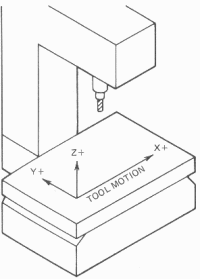
The positive cutter motion directions for a vertical spindle mill are to the right of the operator (X-axis), away from the operator (Y-axis), and up (Z-axis).

| Setting up Milling machine - Position cutter and set cutting depth and width |
| Videos Additional website |
| Finding the exact position on a workpiece where machining must be done is extremely important for accurate machining of components. |
| Which Direction is Which? |
|
Vertical Milling machine The positive cutter motion directions for a vertical spindle mill are to the right of the operator (X-axis), away from the operator (Y-axis), and up (Z-axis).
|
| Horizontal Milling machine Horizontal spindle N/C mills are a little more confusing. For a sense of direction, one must be looking in the Z-minus direction, as if one's eye were stuck in the spindle and looking out at the workpiece. Then the positive cutting tool motion directions are to the right (X-axis), up (Y-axis), and toward the end of the spindle (Z-axis).
|
||||
| Finding the edge of workpiece
Paper
method This method ca n be used to find all sides of the work, including the top of the workpiece. An advantage of this method is that the cutter does not have to be removed from the spindle to do this |
||||
| Wiggler This is a superior form of sticky pin. It consists of a shaft with a ball joint at one end. It usually comes with several different arms that can be fitted to the ball joint. But the most commonly used end is another ball. |
||||
|
|
||||
|
The wiggler will fit
an ordinary collet chuck or drill chuck but it will not fit an Auto-lock
chuck because it does not have the necessary screw thread on it. |
||||
| Wiggler This consists of two round parts held together by a spring. This is fitted in the spindle. The spindle rotates. If the two parts are offset as the workpiece approaches the bottom part, it tends to line up with the top. As soon as the workpiece goes beyond this point the bottom part jumps to one side.
|
| Finding the centre of shaft
for cutting keyways and splines One of easiest methods to find the centre of the shaft is to bring the cutter next to the shaft adjust make it touch the side of the shaft to find a reference face. Adjust the table down so that the cutter clear the shaft. Move the table on the Y axis by half the diameter of the shaft plus half the diameter (thickness) of the cutter
|