Pumps installation
 
Pump placement – general
Place the pump unit on a flat surface that is capable of supporting the load.
  • Make sure the pump unit is placed in such a manner that it is not subjected to any distorting forces.
  • Make sure there is enough space around the pump unit for operation and maintenance.
WARNING:
  • Make sure the top of the pump unit is not covered. This is important because the diesel engine driven pump unit draws in fresh air from the top.
  • Make sure the front and sides of the pump unit are not covered. This is important because the diesel engine driven pump unit expels heat on these sides
General piping guidelines
  • Select the diameter and length of the suction and pressure pipes as well as those of any additional components such that the inlet pressure remains above the minimum allowable value.
  • The operating pressure must not exceed the maximum allowable value. The power rating of the installed drive system must be sufficient. NPSH graphs are available on request.
  • The diameters of the pipes must be equal to or greater than the connection sizes on the pump.
    If possible, the transition between various pipe diameters must be made with a transition angle of approx. 8 degrees.
  • The pipe must be properly aligned with the pump connection.
  • It must be possible to connect the flanges of the pipes and pump together without putting any of the parts under stress.
  • In the case of vibration and/or hot liquids, install expansion elements in the pipes.
    Support the pipes directly in front of the pump. The weight of the pipes and fittings may not be supported by the pump.
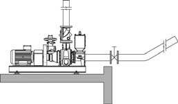
  • Install shut-off valves in the suction and pressure pipes as close as possible to the connection flanges in order to allow isolation of the pump for maintenance and repair work. The shut-off valves must be of a type that allows straight-line flow, such as gate or globe valves. The internal diameter of the shut-off valve must be the same as that of the pipe.
  • If there is a possibility that a backflow of liquid could cause the pump to turn in the opposite direction when stopped, a non-return valve must be placed in the piping to prevent this.
  • Install measurement instruments in the piping for monitoring during operation.
  • If applicable, connect the pump unit to a suitable safety system. This is left to the judgement of the designer of the installation.
  • Insulate or shield hot pipes.
  • Observe specific regulations that pertain to the suction and pressure pipes.
  • Thoroughly clean all parts that come into contact with the transported liquid before putting the pump unit in operation.
Note: When pumping viscous liquids, there can be significant pressure losses in the suction and pressure pipes. Components placed in the piping system, such as shut-off valves, bends, suction strainers, filters and foot valves, will make the pressure losses greater.
 
Suction pipe  
  • Place the pump or pump unit as close as possible to the pumped liquid.
  • The pipe must be as short as possible.
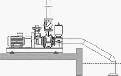
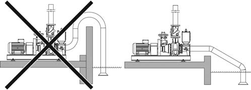
    Run the pipe so it slopes upwards
  • toward the pump to prevent the formation of air pockets.


  • If the pipe tapers, the pipe must slope downwards toward the pump. Place a shut-off valve between the float chamber and MP to prevent overpressure on the MP.

   
  • Lay the pipe so as to prevent the formation of air pockets.
  • Use the least possible number of bends.
  • Bends must have the largest possible radius.
  • The pipe system must be completely airtight.
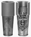
  • In the case of a non-self-priming pump, in which the liquid does not flow towards the pump, install a foot valve with a sufficiently large flow capacity.

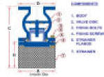
  • In the case of polluted liquids, always install a suction strainer or solids separation screen with a sufficiently large net opening area. The filtration particle size of the suction strainer must be equal to or less than the solids handling specification of the pump.


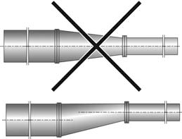
  • When there is a change of diameter in the piping, use an eccentric reducer to prevent the accumulation of air.


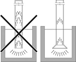
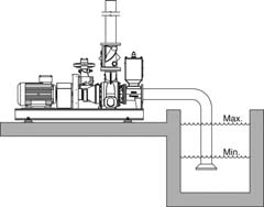
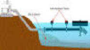
  • Make sure that the liquid intake will remain sufficiently submerged beneath the liquid surface so no air will be drawn in even when the liquid is at its lowest level.


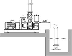
  • Make sure the length of the pipe between a bend and the pump is at least four times the diameter of the pipe, especially when there is little margin between the available and required NPSH. A bend prevents the smooth inflow of liquid to the pump impeller and can have a negative impact on the suction conditions.


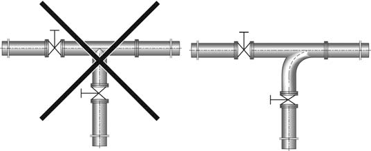
  • When a T-junction is installed, use one with an inflow bend.


In the case of self-priming pumps fitted with a separate suction bend, this bend must never be removed or rotated.
  • For liquids with a low viscosity, either install a foot valve with a diameter equal to or greater than that of the suction valve or install the piping without a foot valve in a U-configuration (see technical specifications BA series).
  • Do not install a foot valve when pumping high viscosity liquids. The foot valve causes extra pipe losses.
  • To eliminate any air or gases present in the pump or suction pipe, the pressure pipe can be fitted with a bypass line. The use of a bypass line will eliminate air from the pump more quickly. See also ‘Pressure pipe’.
  • In some situations the temperature of the liquid may be so high that the pump requires pre-pressure relative to the NPSH in the line (see technical specifications BA series).
Pressure pipe
  • The designer of the installation is responsible for including the safeguards, such as protection against overpressure.
  • To prevent pipe losses, use the fewest number of bends possible.
  • When the pressure pipe is long or when a non-return valve is used in the pressure pipe directly after the pump, install a bypass line, fitted with a shut-off valve. Connect the bypass line to the suction line or suction point.
  • To bleed air from the pump more quickly, the bypass line must be connected to the supply tank or suction point.
WARNING
Prevent sudden closure of the pressure pipe that would cause water hammer.
  • If there is a danger of water hammer, install a bypass, accumulator or pressure safety valve in the pressure pipe.
Suction strainer
When pumping polluted liquid or liquid that may contain solid particles, install a suction strainer in the suction opening.
  • When selecting the suction strainer, carefully consider the mesh width so pipe losses are kept to a minimum. The net opening area of the suction strainer must be at least three times the crosssectional area of the suction pipe.
  • In the case of polluted liquids, always install a suction strainer with a sufficiently large net opening area. The filtration particle size of the suction strainer must be equal to or less than the solids handling specification of the pump.
  • Install the suction strainer such that maintenance and cleaning are possible.
  • Make sure the liquid being drawn in has the expected viscosity and can easily flow through the suction strainer. Heat the suction strainer if necessary.
  • Consult the technical specifications for the BA series for the maximum allowable particle size (solids handling capacity).