|
Thee jaw chuck
Video |
|
|
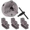
| Three-jaw universal chuck is
used to hold round and hexagonal work. It grasps the work quickly and
within a few hundredths of a millimetres or thousandths of an inch of
accuracy, because the three jaws move simultaneously when adjusted by
the chuck wrench. Three Jaw, self
centring chuck. One jaw has been removed and inverted to show the teeth
that engage with the scroll plate and thereby allow movement. Underneath
the image is the chuck key used to rotate the scroll and therefore
operate the chuck.
|

|
Advantages of three jaw
chuck:
- Can hold hex and round bar-stock
- Quick and easy to use
- Self centring
- Parallel, facing and boring
operations can be done
- Internal and external jaws available
Disadvantages of three jaw chuck:
- Can't hold square bar-stock
- Run-out/off-centre can't be easily
fixed
- Can't hold irregularly shaped work
- Can't run off-centre
|
|
Four jaw chuck |
|
|
| This four- jaw independent
chuck has four jaws; each of which can be adjusted independently by a
chance wrench.
They are used to held wound, square,
hexagonal, and irregular-shaped work pieces. The jaws can be reversed to
hold work by the inside diameter.
|

 |
Advantages of four jaw
chuck:
- Work can be centred to high
precision
- Can handle square/rectangular bar
- can turn work off-centre
- slightly more grip on round stock
- Internal and external jaws available
Disadvantages of four jaw chuck:
- Slower and difficult to mount work
(dial-indicator required)
- can't hold hex-stock
|
|
Faceplate
Video 1
Video 2 |
|
|
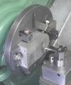
| A lathe faceplate is a basic
work holding accessory for a centre lathe. It is a circular metal
(usually cast iron) plate which fixes to the end of the lathe spindle.
The work piece is then clamped to the faceplate, typically using t-nuts
in slots in the faceplate, or less commonly threaded holes in the
faceplate itself. It may be
necessary to use counter balancers when there is vibration.
An angle pate can also be used on
faceplate when a part such as a pedestal bearing has to be machined. |

 |


 |
| |
|
|
|
Collet chuck
Video |
|
|
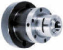
| The three-jaw powered chuck
is the standard work holding device for most lathe users. This
type of chuck is versatile enough to be used in a wide range of turning
applications. However, it's not the best chuck for all jobs. The Collet
chuck is an alternate work holding device that, like the jaw chuck, also
uses mechanical force to hold the part being turned. While a Collet
chuck lacks the capacity for the same wide range of work piece sizes
that a jaw chuck can accommodate, it offers advantages related to speed,
accuracy and productivity that may be crucial for certain jobs.
Collet chucks cater for standard stock
material such as 6 mm, 8 mm etc round bar.
|
Collet Chuck Advantages
- Light weight
- Fast acceleration
- Less affected by centrifugal force
- Tight concentricity
- Fast clamping
- Fast Collet change for part
changeover
Collet Chuck Drawbacks
- Limited range of work piece sizes
- Large axial dimension
- Better suited to small parts
- Better suited to work pieces with
consistent diameter
|

 |
|
Mandrels
Additional website
Video |
|
|
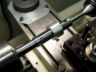
Sometimes it is necessary to
machine the outer surfaces of cylindrical works accurately in relation
to a hole concentric that has been previously bored in the centre of the
work. In such cases the work is mounted on a device known as a mandrel.
Lathe mandrels are devices used to hold the job for machining on lathes.
They are mainly used for machining outside diameters with reference to
bores which have been duly finished by either reaming or boring on a
lathe.
|
Types of mandrels
|
 |
|
Driving Plate (Catch pate) |
|
|
| Catch plates are either
screwed or bolted to the nose of the threaded, stock spindle. A
projecting pin from the dog fits into the slot provided in catch plate.
This imparts a positive drive between the lathe spindle and work piece. |
|
|
