|
SUBJECT
OUTCOME |
| 4.1
Use a centre lathe to produce a component |
| |
|
|
Explain the purpose of using
a centre lathe
-
With the aid of sketches the parts and components that
make up the lathe.
-
The different turning operations that can be performed on
a lathe and where relevant the advantages
and disadvantages.
|
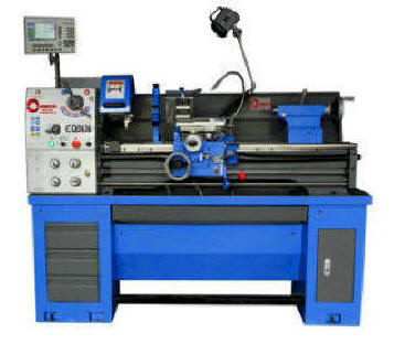
| The Centre Lathe. The Centre
Lathe is used to manufacture cylindrical shapes from a range
of materials including; steels and plastics. Many of the
components that go together to make an engine work have been
manufactured using lathes.
A lathe is a machine tool that
carries out many machine shop tasks. ... The lathe holds and
rotates the work piece about the centre line of these two
parts. It can also machine a part between its headstock and
tailstock centres. This is why we call it a centre lathe.
Video
Additional website 1
Additional website 2
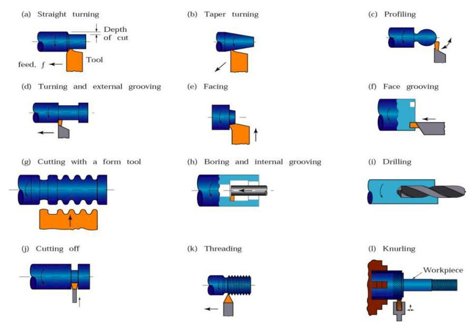
- Parallel turning
- Facing
- Drilling and reaming
- Boring
- Taper turning
- Internal and external
thread cutting
- Knurling
- Grooving
- Parting
- Profile (contouring)
cutting
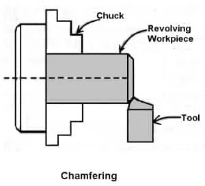
- Chamfering
 |
| |
|
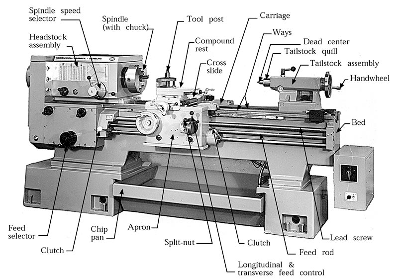
Centre lathe parts |
| |
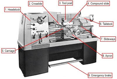
| There are many types of
lathe machine but each machine consist some basic part which
are essential for its proper working. These parts are bed,
tool post, Chuck, head stock, tell stock, legs, Gear chain,
lead screw, carriage, cross slide, split nut, apron, chip
pan, guide ways etc. |
| |
|
 |
| |
|
Headstock |
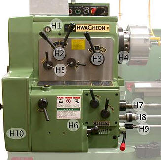
| Head Stock The main function
of headstock is to transmit power to the different parts of a lathe. It
comprises of the headstock casting to accommodate all the parts within
it including gear train arrangement. The main spindle is adjusted in it,
which possesses live centre to which the work can be attached.
Different clamping components can be
attached to the spindle to hold work.
- It can adjust the spindle speed
- Adjustment for feed screw for thread
cutting
- Feed adjustment for automatic feed
- Emergency stop button
- Cutting fluid pump switch
|
 |
|
Headstock spindle |
|
The spindle is the hart of
the centre lathe. It is rotating by means of the headstock motor
through the gearbox. It can rotate in both directions. It
can accommodate various clamping devices such as:
- Three jaw chuck
- Four jaw chuck
- Faceplate
- Dead centre for turning between
centres
- Collet
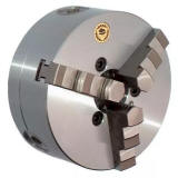
Thee jaw chuck
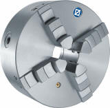
Four jaw chuck |
 |
| |
|
|
Tailstock |
|
| It is usually used to apply
support to the longitudinal rotary axis of a work piece being machined.
A lathe centre is mounted in the tailstock, and inserted against the
sides of a hole in the centre of the work piece.
It can also accommodate the following:
- Drill bits for drilling
- Reamers for reaming
- Taps for cutting thread
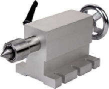 |
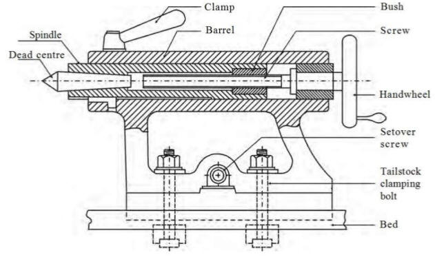
|
| |
|
|
Lathe bed and gap bed |
|
| The lathe bed is made from
cast iron and form a large part of the lathe. The lathe size are
express as the length of the bed. To be more precise the maximum
distance between the tailstock and headstock.
The bed supports he carriage as well as the
tailstock.
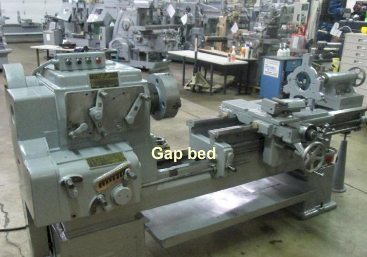
Gap bed is a piece of bed that can
be removed close to the headstock to accommodate work with large
diameter.
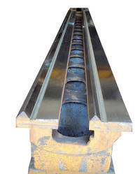
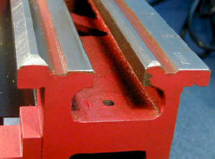
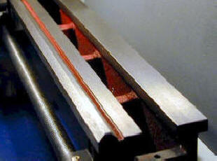
The bed can come in the following guides:
- Flat bed
- V-flat bed
- V-V bed
|
V-V bed |
V-flat bed |
 |
| |
|
|
Carriage |
|
| The carriage houses the
saddle, the cross slide, and the apron. The main function of the
carriage is to position the tool along the lathe bed. This lever
controls the spindle's rotation and direction.
The following components make up the
carriage:
Saddle - Fit
on top of the bed and is accurately guided by the v-shaped guides in the
bed.
Cross slide is fitted to the
saddle and accommodates movement at right angels to the bed of the
lathe.
Compound
slide (or top slide) is usually where the tool post is mounted.
It provides a smaller amount of movement (less than the cross-slide)
along its axis via another feed screw. The compound rest axis can be
adjusted independently of the carriage or cross-slide. It can be set to
angels to accommodate internal and external tapers to be cut. It
also facilitate for the cutting of V-thread.
Tool post
is used to hold tools for turning and facing, boring, and knurling.
Quick change tool posts are specifically designed for the mini lathe and
may include a tool post and tool holders.
Apron is the
front face of the carriage. It is where the feed controls are located on
most manual lathes. The apron is also a housing for the gears and
associated mechanisms related to power feeding of the carriage and cross
slide |

|
| |
|
Feed shaft |
|
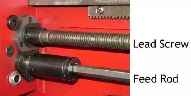
| The feed shaft (rod)
is a power transmission mechanism used for precise linear movement of
the carriage along the longitudinal axis of the lathe. This is
used to for automatic feed. The engagement levers is situated on
the apron
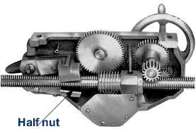
Lead screw The lead screw
of a lathe is used to advance the carriage of the lathe in time with the
rotation of the spindle. It is used to make threads by having different
gearing between the spindle and the drive for the lead screw. The half
nut on the apron is used to engage the lead screw.
 |
 |
| |
|
| Foot brake (emergency brake) |
|
| All lathes should be fitted
with emergency stop, foot or knee switches.
In case of an emergency even if hands are
tied up, all you need to do is to step on the foot brake.
The foot brake will cut the power and a
disk brake on the motor shaft will stop the rotation of the spindle.
NOTE: This brake is only for emergency
and not to be used for normal operation as this will put unnecessary
strain on the drive train of the lathe. |
|
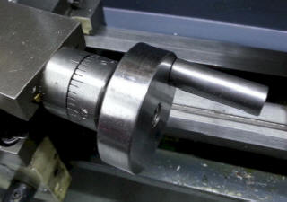
| Graduated hand wheels |
|
| |
|
|
|
| Parallel turning
Video
Additional website |
|
Face turning
Video |
|
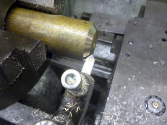
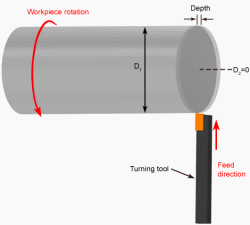
| Parallel turning is done
along the length of work. A single-point turning tool moves
axially, along the side of the work piece, removing material to form
different features, including steps, tapers, chamfers, and contours.
These features are typically machined at a small radial depth of cut and
multiple passes are made until the end diameter is reached.
|
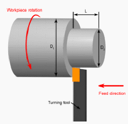 |
A single-point turning tool moves radially, along the end of the work
piece, removing a thin layer of material to provide a smooth flat
surface. The depth of the face, typically very small, may be machined in
a single pass or may be reached by machining at a smaller axial depth of
cut and making multiple passes.
|
 |
| |
|
|
|
| Taper turning external
Video
Additional website |
|
Taper turning internal |
|
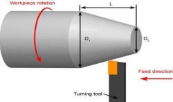
| A taper is a conical shape.
Tapers can be cut with lathes quite easily. There are some common
methods for turning tapers on an centre lathe,
Using a form tool: This type of tool is
specifically designed for one cut, at a certain taper angle. The tool is
plunged at one location, and never moved along the lathe slides. v
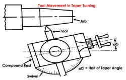
Compound Slide
Method: The compound slide is set to travel at half of the taper angle.
The tool is then fed across the work by hand, cutting the taper as it
goes. v Off-Set Tail Stock: In this method the normal rotating part of
the lathe still drives the work piece (mounted between centres), but the
centre at the tailstock is offset towards/away from the cutting tool.
Then, as the cutting tool passes over, the part is cut in a conical
shape. This method is limited to small tapers over long lengths. The
tailstock offset h is defined by
h = Lxsinα, where L is the length of work piece, and α is the half of
the taper angle.
|
 |
Internal tapes can also be
machined on a centre lathe. You are limited to only using the compound
slide method or the taper turning attachment method.
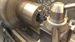
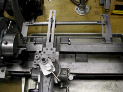
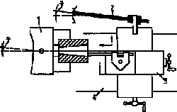
Taper Turning Attachment is very much
popular and fits on all lathe machine. In ordinary straight turning, the
cutting tool moves along a line parallel to the axis of the work,
causing the finished job to be the same diameter throughout.
|
|
| Screw cutting
Video |
|
Parting off and Grooving
Video |
|
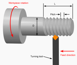
| A turning operation in which
a single-point tool, typically with a 60 degree pointed nose, moves
axially, along the side of the work piece, cutting threads into the outer
surface. The threads can be cut to a specified length and pitch and may
require multiple passes to be formed.
Square, ACME and buttress thread can also be
cut.
Internal as well as external thread can
be cut.
|
 |
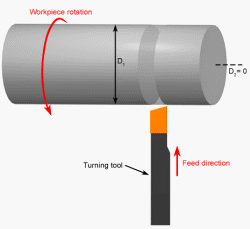
A turning operation, also
known as parting, in which a single-point cut-off tool moves radially,
into the side of the work piece, and continues until the centre or inner
diameter of the work piece is reached, thus parting or cutting off a
section of the work piece. A part catcher is often used to catch the
removed part. A turning operation
in which a single-point tool moves radially, into the side of the work
piece, cutting a groove equal in width to the cutting tool. If
the desired groove width is larger than the tool width, multiple
adjacent grooves will be cut. A profiling cut can be performed to smooth
the surface of multiple grooves. Special form tools can also be used to
create grooves of varying geometries. |
 |
| |
|
|
|
| Profile turning
Video |
|
Drilling
Video |
|
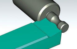
| Profile turning is normally
done with a cutting tool that has been shaped according to the profile.
The cutting tool is difficult to make and is
time consuming.
|
 |
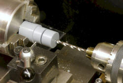
The tailstock of a lathe can
be used for drilling, with the aid of a drill chuck or directly in the
tailstock spindle. If a long
piece of material has to be turned on a lathe then a centre drill is
used to produce the hole at one end. This allows the drilled end to be
supported by the tailstock centre. |
 |
| Boring
Video |
|
Knurling
Video |
|
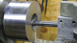
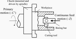
| Boring is the process of
enlarging a hole that has already been drilled (or cast) by means of a
single-point cutting tool (or of a boring head containing several such
tools), such as in boring a gun barrel or an engine cylinder.
 |
 |
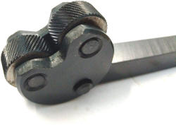
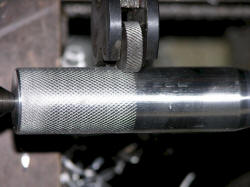
A knurling tool is used to
press a pattern onto a round section. The pattern is normally used as a
grip for a handle. Apprentice engineers often manufacture screwdrivers.
These have patterned handles, to provide a grip and this achieved
through the technique called knurling.
 |
 |


