| Videos Additional website | ||||||||||||||||||||||||||||||||
| Hydraulic circuits transmit and control power from a mechanical input to a mechanical output by means of liquids, mostly oils. Power is transmitted hydrostatically, where high pressures make static forces dominate over dynamic forces, and energy is transmitted mostly through static pressure at low flow velocities. | ||||||||||||||||||||||||||||||||
| Circuits are composed of a number of hydrostatic components which are connected to each other by means of piping, manifolds, or directly, to enable transmission and control of power or signals through liquids. | ||||||||||||||||||||||||||||||||
| Hydraulic circuits can be represented in various ways: | ||||||||||||||||||||||||||||||||
|
||||||||||||||||||||||||||||||||
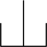
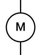
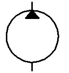
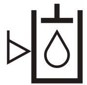
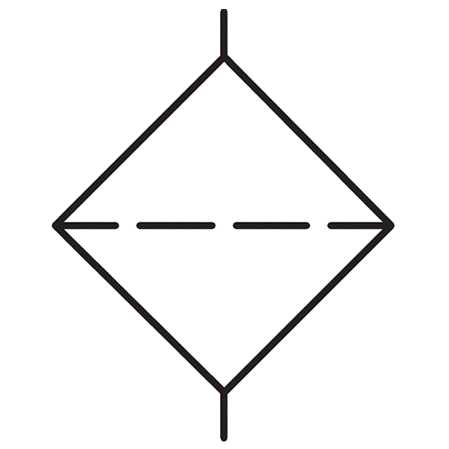
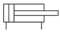
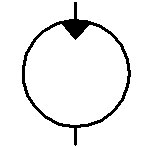
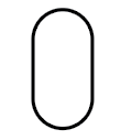
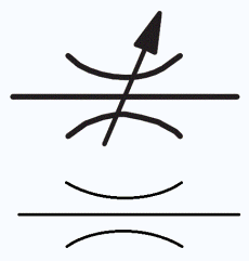
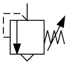
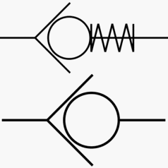
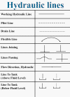
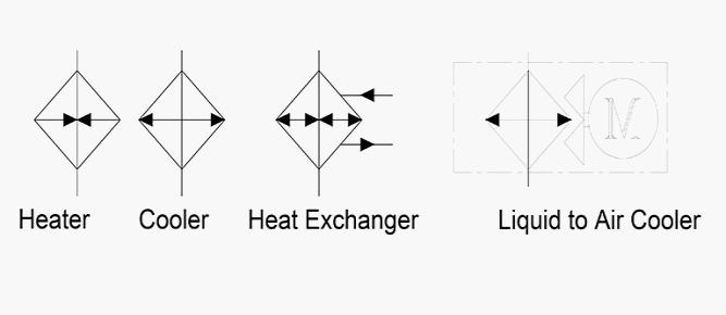
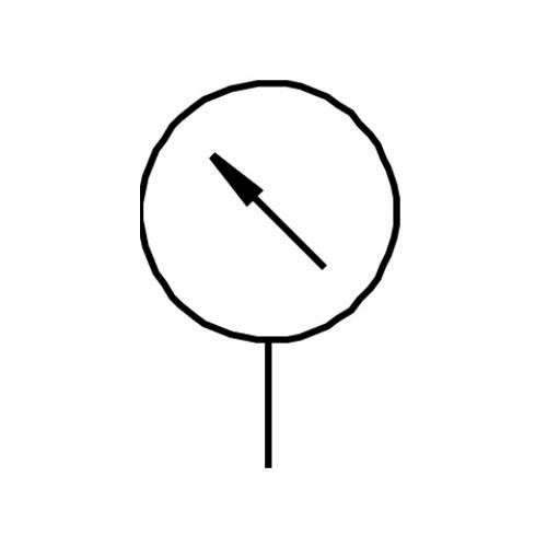
| The most common representation of hydraulic circuits is the graphical system. It is important to know and understand the different symbols. | ||||||||||||||||||||||||||||||||
| Here is a list of the most common hydraulic symbols and there meaning: | ||||||||||||||||||||||||||||||||
|
||||||||||||||||||||||||||||||||
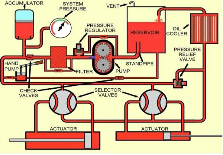
| Example of a typical hydraulic circuit in drawing: | ||||||||||||||||||||||||||||||||
|
|
||||||||||||||||||||||||||||||||
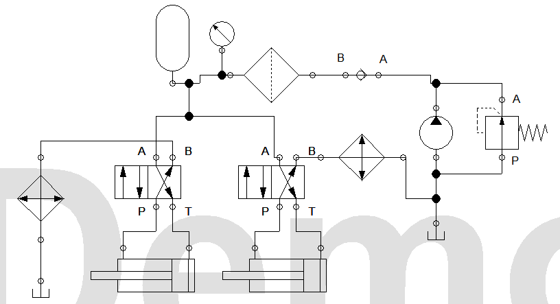
| Same Example of a typical hydraulic circuit in symbols: | ||||||||||||||||||||||||||||||||
|
|
||||||||||||||||||||||||||||||||

TVET COLLEGE SUPPORT
HYDRAULICS
Hydraulic circuits
